Ladder Diagram Of Stop Start Station Motor Ladder Plc Logic
Plc ladder logic on an arduino: building a start-stop circuit Motor control jog circuit circuits diagram schematic power operation Manual start stop station
Draw A Schematic Diagram Of Simple Start Stop Motor Control Circuit
Start stop station schematic Motor start stop ladder logic plc programming tutorials for beginners Plc program for motor starter instrumentation tools
[diagram] one line diagram 3 wire start stop station
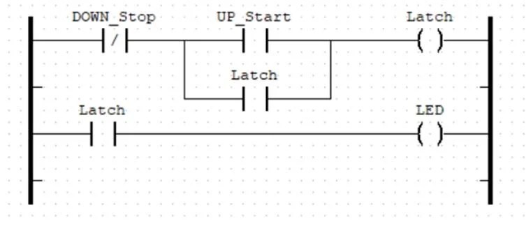
Plc program example with toggle or flip-flop functionPlc rangkaian kontrol star delta ladder diagram mad elektro Solved typical start/stop motor circuit ladder diagram: stopStart stop motor control ladder diagram archives – upmation.
Plc ladder logic on an arduino: building a start-stop circuitSiemens plc ladder diagram 3 wire stop start wiring diagramLadder logic plc flip flop programming circuit siemens simulator programs.

Jog motor control
Understanding motor starters and ladder diagrams: aLadder timer plc diagram delay motor control start siren logic warning Ladder logic hvac schematic relay plc conditioning basic circuit elevator manufacturing shown programmableEmergency stop relay wiring diagram.
Plc ladder diagram examples[diagram] electrical circuit diagram start stop Ladder plc logic control diagram conditional circuit program start stop wire motor pump wiring programming logicsPlc timer.

Motor control ladder diagrams
Single push button start/stop ladder logic diagram using siemens tia portalDraw a schematic diagram of simple start stop motor control circuit Plc program example with toggle or flip-flop functionStart stop wiring schematic.
[diagram] starter motor circuit diagramPlc normally circuit pressed instrumentationtools because 3 wire start stop ladder diagram[diagram] one line diagram 3 wire start stop station.

Ladder diagrams
Start stop circuits- a brief introduction into its components, workingOut of this world motor ladder diagram making 2 prong outlet into 3 .
.


PLC program example with toggle or flip-flop function | Ladder logic
PLC Ladder Logic on an Arduino: Building a Start-Stop Circuit

PLC Program for Motor Starter Instrumentation Tools

PLC Timer - Ladder Logic World

Draw A Schematic Diagram Of Simple Start Stop Motor Control Circuit

Single Push Button Start/Stop Ladder Logic Diagram using Siemens TIA Portal

PLC Ladder Logic on an Arduino: Building a Start-Stop Circuit

Motor Control Ladder Diagrams